FreeCAD

1148 readers
1 users here now

Your own 3D parametric modeler.

www.freecad.org

FreeCAD is an open-source parametric 3D modeler made primarily to design real-life objects of any size. Parametric modeling allows you to easily modify your design by going back into your model history and changing its parameters.

founded 3 years ago
MODERATORS
1


cross-posted from: https://sh.itjust.works/post/50842014

When I moved into my home many years ago, there was this lock-box mounted to the water main on the side of the house. I figured it was one of those used by real-estate agents to store the house key for viewings, but months passed and it still remained there. No one from my buyer's agent's office had a clue what this was, and the seller of the house had already moved out-of-state.

Recently, I had some plumbing work done, and that also included replacing the main water valve for the house, allowing this lock box to come free from the plumbing. Now inspecting it up close, and looking up the model online, I realized that it has an alphabet wheel and uses a three-letter combination.

As it happens, Thanksgiving weekend was upon me, and since I was bored, I figured I'd try all the possible combinations. Just 17,576 possible combinations, how bad could it be?

The most immediate problem was that due to being out in the elements, the dial did not turn easily. It would move, but was rather rough. And since the knob is only ~1 cm diameter, this is an incredibly un-ergonomic endeavor. I had to stop after the first 100 tries, due to the finger exhaustion.

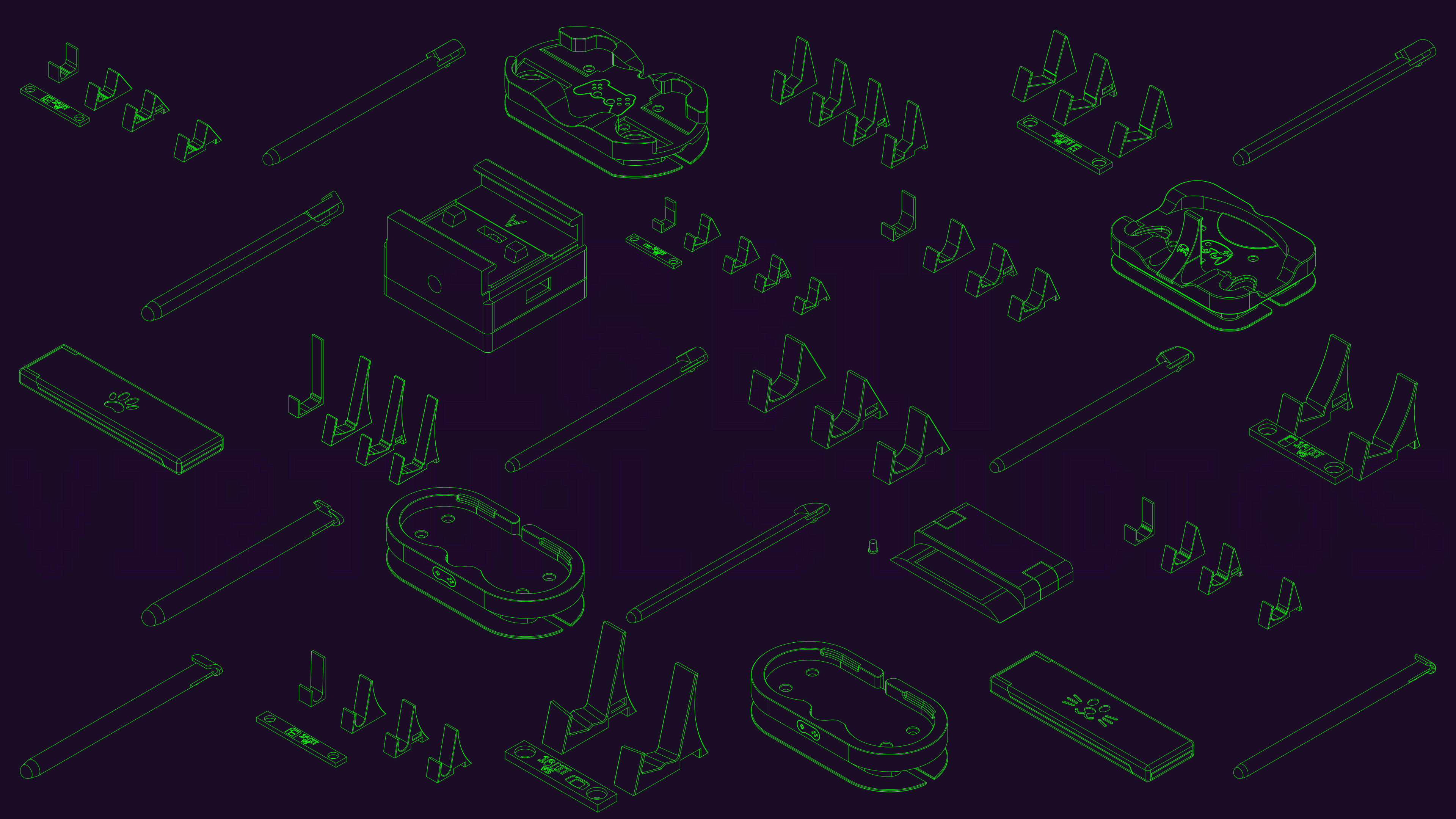
Knowing this would be untenable for the long-run, I decided to build my way out of this problem. Since a combo lock involves making rotations that almost go all the way around, I drew inspiration from rotary telephone dials, where one's finger starts with the intended number and then swivels the dial around.

But whereas a rotary telephone dial only needs 10 positions, I needed to fit 26 positions, one for each letter. I decided on each hole being 17 mm to comfortably fit any of my fingers, but that also dictated the overall diameter of the wheel. But that's good, since a larger diameter wheel means more leverage to overcome the rough lock movement. It also happens to be that this wheel has a diameter of 180 mm, which is just enough to fit in the 200 mm bed of my 3d printer.

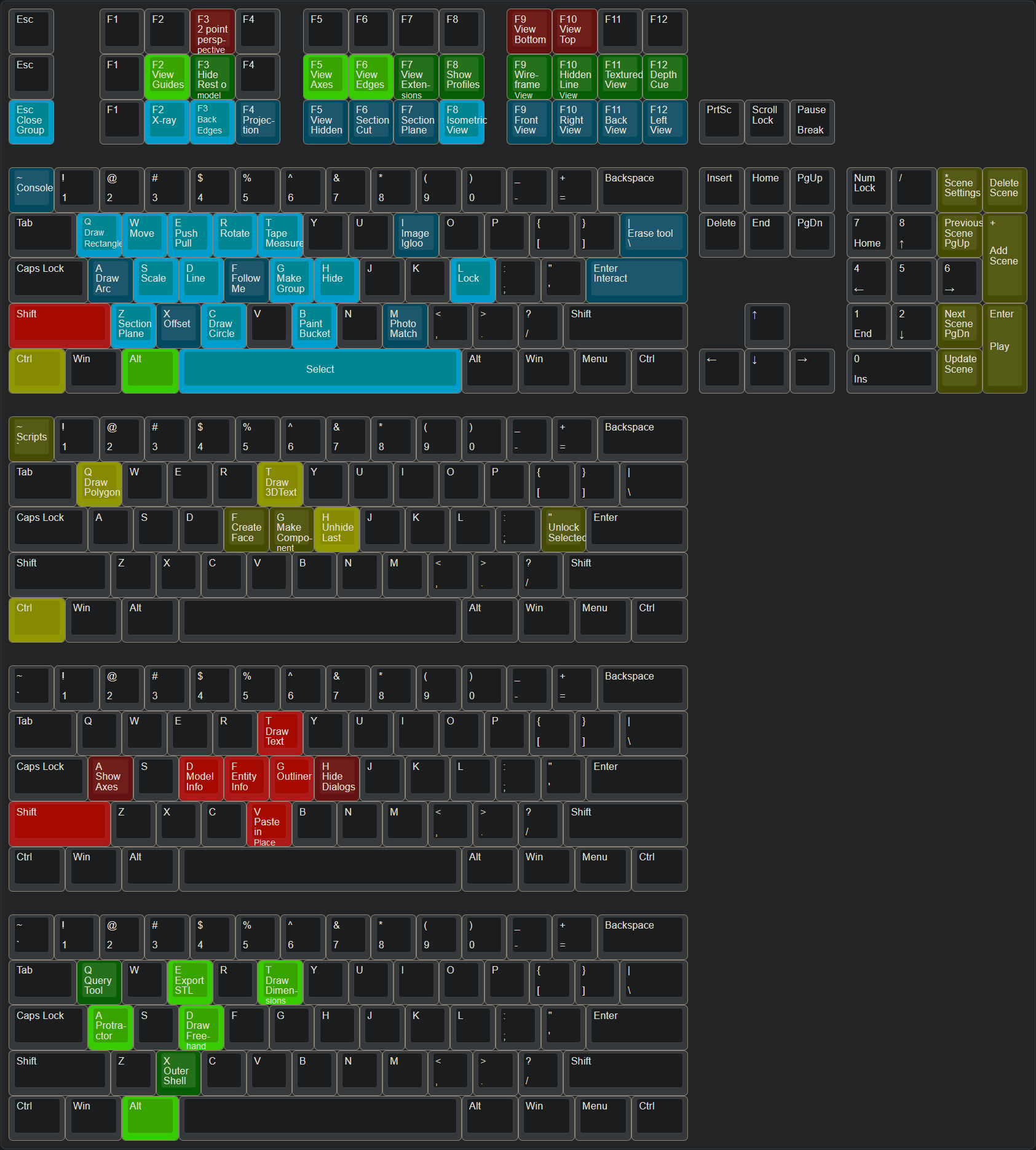
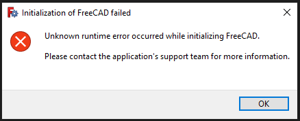
Using FreeCAD, I designed this wheel so that it fits around the splines of the lockbox dial, which held remarkably well. I had thought I would need Blu Tack or something to keep it together.

CAD design for lockbox dial wheel

Using this wheel, I'm able to "dial" combinations much quicker using one hand, while holding the lockbox with my other hand to press the lever down to test the combination. This should be good.

(note: some parts of this story were altered to not give away identifying details)

2


This article will show how to model sheets of Expanded Metal in FreeCAD, without slowing (or killing) FreeCAD.

Troubleshooting Large File Sizes in FreeCAD

Who is Eco-Libre?

Eco-Libre is a volunteer-run project that designs libre technology for sustainable communities.

Eco-Libre's mission is to research, develop, document, teach, build, and distribute open-source technology that sustainably enfranchises communities' human rights.

We aim to provide clear documentation to build low-cost machines, tools, and infrastructure for people all over the world who wish to live in sustainable communities with others.

Contribute to Eco-Libre

If you'd like to help Eco-Libre reach our mission to enfranchise sustainable communities' human rights with libre tech, please contact us to get involved :)

Join Us
eco-libre.org/join

Cheers,
The Eco-Libre Team
https://www.eco-libre.org/

3


This article will show you how to find out exactly which layer is causing your FreeCAD file to balloon in size, by getting a granular list of all of the layers in your document tree, sorted by size.

Troubleshooting Large File Sizes in FreeCAD

Who is Eco-Libre?

Eco-Libre is a volunteer-run project that designs libre technology for sustainable communities.

Eco-Libre's mission is to research, develop, document, teach, build, and distribute open-source technology that sustainably enfranchises communities' human rights.

We aim to provide clear documentation to build low-cost machines, tools, and infrastructure for people all over the world who wish to live in sustainable communities with others.

Contribute to Eco-Libre

If you'd like to help Eco-Libre reach our mission to enfranchise sustainable communities' human rights with libre tech, please contact us to get involved :)

Join Us
eco-libre.org/join

Cheers,
The Eco-Libre Team
https://www.eco-libre.org/

4


If you wanna print it yourself, the model is here: https://www.printables.com/model/1348194-4n-threaded-flat-head-screws-and-nuts-10-32-equiva

Design to be a drop in replacement for 10-32 screws with a much, much higher pitch. These screws are extremely easy to print, is reliable enough that it can hold some weight.

If you wanna print this yourself, you need to make sure that the screw is sideways, so if it breaks it's no on the layer lines.

Using them in my own prints which had metal screws and they are holding quiet well.

5


The Subtractive Helix is broken and very buggy. But it is the most reliable way to get a screw and nut in the software.

6
1
submitted 7 months ago* (last edited 7 months ago) by MxRemy@piefed.social to c/freecad@lemmy.ml


Finally managed to actually design, CAM, and post process something all with just FreeCAD! Just a simple sign for a library patron. This finished item obviously still has lots of issues but they're mostly user error and I think I know how to fix them. HUGGGEEE thanks to clsergent for designing a postprocessor for Snapmaker machines, since the company hasn't bothered to maintain theirs for like years and years lol.

Overall couldn't be more satisfied, 10/10, FreeCAD is amazing 🔥

7


I think opened a debug console or something.

8


The .stl and .fcstd files are at the link. All the test joints I printed fit together really nicely, but I'm worried the overall design might have issues that I'm too much of an amateur to identify. It'll need a LOT of filament... Good wooden marudai cost hundreds of dollars, whereas 1500g of my preferred filament is only like $45, but I'd still hate to waste that much of it. The printing itself I'm not too concerned about, it's easy stuff. Just a little bridging and no support. Of course, that doesn't necessarily mean the finished/assembled object will be functional. Thanks in advance if you have any tips!

PS: This is also my first use of the spreadsheet function, I usually just rely on named constraints from prior sketches. It's really neat. FreeCAD rules!

9
10


I’ve tried the dev branch of FreeCAD for a while now, but backed off due to how unpolished it felt. But when I saw FreeCAD V1 RC2 pre-release on GitHub Id thought to try it out.

My first impressions didn’t blow me away, sure there were nice UI touches here and there. But nothing really stood out to me. But that changed when I started cading.

It’s not a major overhaul to my eyes. But the nice touches are everywhere. Like adding a TinkerCAD navigation controls option for beginners, and smart snapping and auto constraints enabled by default. So, so nice especially for noobs who don’t know that >.< is a centre constraint in the tool bar.

But I had a quick project, tonight. Redesign an older model from scratch to add in new parts. My original designs were some of the first real work I did in FreeCAD so it was nice to see the improvements. Out side of legacy bugs like attaching a 3 point arc to a line still being present, the process was smooth, not as pain free as Fusion, but better.

Then at the end when I was adding text to my part. I got to see the best update of them all. If you aren’t aware, adding text to a model is annoying. Especially if you want it a distance from a side or in the middle. You needed to use the measuring tool to get deltas and re measure after every change. I was using the new measuring tool like that too, and thank you devs for adding manual controls and deltas. But at the end, I left the measurements on the text, updated the values, and noticed the numbers updated on me… OMG best feature of all time 10/10 best CAD software in the world. This makes my life soooooo much easier now.

If you haven’t already try the RC versions of FreeCAD do so. Sure there is still some open source jank in it, but it’s so much more polished than before that I feel this upcoming release deserves the V1 moniker.

11


Maybe there's something I don't understand here. I'd love it if someone told me how to do the following.

Let's say I have some really complex shape in a sketch left of the Y axis: it takes me forever to get it just right. Then I need to mirror it on the right side of the Y axis and connect the two halves.

In SolidWorks, it's trivial: mirror the stuff, done. If you change the master shape on the left, the change is reflected on the right.

In FreeCAD, the best you can do is make a mirror copy of the left-hand side elements - which also makes copies of the constraints which are completely independent from the original constraints on the left-hand side - delete the stupid new right-hand side constraints and slowly, painfully constrain the right-hand side copies to the original left-hand side elements, trying to dodge the dreaded orange over-constraints all the time. It's long, it's painful, and the end-result is usually so fragile that if you change anything significant on the left-hand side, the sketch turns orange and then it's back to hunting broken constraints again.

Surely it can't be that painful. Am I missing something obvious?

12


Thank you FreeCAD for not pay walling the ability to create technical drawings.

So what I did to make this was to create a technical drawing of all the designs I wanted and I made this photo in Inkscape.

Was designed to be a banner for my social media, but loved it so much that I'm just using it as my desktop wallpaper.

13


Hey everybody,

After a few months without using FreeCAD (but keeping up with the daily updates) I need to model a quick something today.

And I realize there seems to be a new feature in the 0.22.0-dev version that prevents me from orbiting around the model when I'm in the sketcher:

I use OpenSCAD-style 3D navigation, which means I left-click to rotate the model. In the sketcher, left-clicking is used to do a rectangular lasso selection, and that prevents me from orbiting around the model. I tried with shift, ctrl, alt and all combinations thereof, but there seems to be no way to disable that selection feature.

Fortunately I also use a 3DConnexion Spacemouse, so I'm not completely stuck, but it's kind of annoying to have to use that thing when I'd rather not move my hand away from the keyboard.

Anybody knows how to disable the lasso thing?

14


Anyone aware of a target date for when FreeCAD 1.0 and/or Ondsel 2024.3 will be released?

Background:

I'm coming from using onshape, looking for a local opensource alt. After researching freecad (and forks) it seems if I was to start learning now, I'm in for a significant shift in workflow when 1.0 releases.

In its current state I'd lean towards ondsel.

Kind of putting off the switch till one or both implement the topo naming fix, and the other major ui changes for mainline, so I don't need to learn two different workflows.

But I'm getting antsy and want to get learning soon.

15


Hey, I've just finished my diploma of mech eng and them and my new workplace use largely solidworks. Solidworks might have the most annoying subscription service integration I've ever seen, but also I've clicked with its interface.

Any guides or tips for switching over?

16


Hi c/FreeCAD, totally newbie here! I'm having a ton of fun learning FreeCAD, but I have a small question. I know the toponaming problem is going away soon, and maybe that makes this kind of irrelevant, but I'd still like to know.

Sometimes when I'm watching or reading guides on avoiding the toponaming problem, the person will say something along the lines of: "actually this technique is also more professional/proper/correct anyway, real engineers do it this way." Basically that the methods that avoid the problem are also just best practices in general. But they always say that as kind of an aside, and I wish they'd say more! What makes those methods better? Does anyone have any suggestions for articles or videos about this?

For one example, there was one guide that suggested you should use a datum plane instead of referencing one of the object's surfaces. I understand the toponaming problem well enough to get why referencing a surface can cause it. However, the person in the guide used the same surface that would have been referenced, as the attachment point for the datum plane. Why does that not produce the same issue?

17


The contest from last month had established five finalists:

The first row is the new logo that will be used going forward and in version 1.0 of the program!

18


In other cad programs i use two points of a sketch to extrude a feature. In freecad it does not seem to be possible. What are your recommended workarounds for that?

I would like to extrude the base not just from the face of the sketch, but from point 1 to point 2 on the side view sketch. This workflow proved very robust in other cad tools, but I cant get it work in freecad.

Thanks a lot in advance!

19


And I'm curious if I could map my keys to make Freecad work this way. I don't know how many of the these tools don't exist in Freecad, but if I could one to one make a keybind that works for me, I might start using it instead of sketchup 8

But mostly, this is the because general CAD community on lemmy and I wanted to share, ciao!

20
1
submitted 2 years ago* (last edited 2 years ago) by RandomLegend@lemmy.dbzer0.com to c/freecad@lemmy.ml


Hello,

so i just started to do some macro writing and had to get some help by ChatGPT because i am no programmer. But i made something useful for me.

import FreeCAD
import PartDesignGui
import Draft
import Part
import PartDesign
from FreeCAD import Base

doc_name = App.activeDocument().Label

sels = FreeCADGui.Selection.getSelectionEx('', 0)
facebinder1 = Draft.make_facebinder(sels[0])
facebinder2 = Draft.make_facebinder(sels[1])
Draft.autogroup(facebinder1)
Draft.autogroup(facebinder2)
FreeCAD.ActiveDocument.recompute()
App.getDocument(doc_name).addObject('Part::Loft','Loft')
App.getDocument(doc_name).ActiveObject.Sections=[App.getDocument(doc_name).Facebinder, App.getDocument(doc_name).Facebinder001, ]
App.getDocument(doc_name).ActiveObject.Solid=True
App.getDocument(doc_name).ActiveObject.Ruled=False
App.getDocument(doc_name).ActiveObject.Closed=False

I select two faces from two bodies and it will create two seperate facebinders and performs a loft with those two.

This allows me to make a loft in one fell swoop. However the facebinders created by the

Draft.make_facebinder(sels[X])

will always come out as Facerbinder and Facebinder001 and counting upwards. I don't see any way to change those names. Yes, i can do something with labels, but the following part of

App.getDocument(doc_name).ActiveObject.Sections=[App.getDocument(doc_name).Facebinder, App.getDocument(doc_name).Facebinder001, ]

doesn't seem to work with labels... As you can see Facebinder and Facebinder001 are hardcoded in there. Is there any way to either fully rename items so i could go for facebinder_temp1 and _temp2 and then rename them afterwards to make room for another _temp1 and _temp2 again or if i can somehow let the Loft function know what Facebinders were created prior?

Sorry if this is a little bit unstructured i am bashing my head right now... maybe you can help me out here.

Thanks!


EDIT:

Solution was:

# -*- coding: utf-8 -*-

# Macro Begin: /home/frank-garuda/.local/share/Ondsel/Macro/asfasdf.FCMacro +++++++++++++++++++++++++++++++++++++++++++++++++
import FreeCAD
import PartDesignGui
import Draft
import Part
import PartDesign

# Gui.runCommand('Std_DlgMacroRecord',0)
### Begin command Part_Loft
from FreeCAD import Base

# Get document name
doc_name = App.activeDocument().Label

# Gui.runCommand('Std_DlgMacroRecord',0)
### Begin command Std_Workbench
# Gui.activateWorkbench("DraftWorkbench")
### End command Std_Workbench
### Begin command Draft_Facebinder
sels = FreeCADGui.Selection.getSelectionEx('', 0)
facebinder1 = Draft.make_facebinder(sels[0])
facebinder1.Label = "Facebinder_Loft_1"
facebinder2 = Draft.make_facebinder(sels[1])
facebinder2.Label = "Facebinder_Loft_2"
Draft.autogroup(facebinder1)
Draft.autogroup(facebinder2)
FreeCAD.ActiveDocument.recompute()
App.getDocument(doc_name).addObject('Part::Loft','Loft')
App.getDocument(doc_name).ActiveObject.Sections=[facebinder1, facebinder2, ]
App.getDocument(doc_name).ActiveObject.Solid=True
App.getDocument(doc_name).ActiveObject.Ruled=False
App.getDocument(doc_name).ActiveObject.Closed=False
21


Hi! I started to fiddle around with freecad a little again tonight. I still find many things unintuitive. And I just watched a video about master sketches, because they are essential in my workflow on other programs. It makes it soo much easier to keep the overview and change little things quickly because I don't have to search for the responsible sketch.

In this video the person demonstrates at around 9:15 how to use the master sketch as a reference in the sub bodies. I can get used to only get one body from a sketch, but man, how many steps does it take to just reference a sketch?! You even need to use a differen workbech, use the clone tool, but not this one and then drag and drop the duplicate into the same body you are working on? Why?! I mean the sketch is right there, just let me click it!!

This got me wondering it those rough workflows are just designed badly or if this is a limitation of the engine or whstevery it's called, that freecad is based on? Because in my limited programming mind it does not make a difference what file is referenced. If it is some file on a directory above, just use something like "./" Before to go up one directory.

And I think those little things that just work in other cad software, makes freecad so much less approcavhabel and so much harder to jump in.

If I want to make a complicated part, that is not just a box with a hole, I don't want to Google around until I found a solution, I want the intuitive solution to work without 3 extra steps. This just hinders my design process a lot.

Maybe someone knows how freecad works on the background and can explain why freecad works like that.

Thanks!

22


Hey there! I love the idea of freecad. But I have so many troubls learning it. I started with fusion360, used solidworks for some time, used inventor a bit and use onshape mostly now. So I think I know how to navigate and learn new cad software. But its not as easy with freecad sadly.

I Would love this product to be more accessable and easier to use and undertand. What can we do besides jumping in on developing ourselves?

Switching form fusion or onshape to freecad feels like switching from python to assamlby.

So how can we help to improve freecad and make it a more usable program? It seems as if the devs try to reinvent everything and every menue compared to all other cad programs i have used. I am totaly fine with some issues or bugs, but i feel like its not up for success currently.

Thanks a lot, I hope you have some ideas

23


Has anyone encountered this issue when launching the software?

The only fix I've found so far is to uninstall and reinstall FreeCAD. Is there a better way to fix this? I wish the error message was more descriptive...

Edit: It seems that I can only launch FreeCAD by ticking the "Launch FreeCAD" checkbox in the initial installation wizard. All subsequent attempts to launch FreeCAD seem to fail. I can uninstall the software without removing my user preferences, so it's not terrible, but having to reinstall the software every time I want to close and reopen the software is a bit... undesirable.

Edit2: If it helps narrow things down, I'm on a Windows 10 machine.

Edit3: I found a forum thread with a workaround. For some reason, right-click and "Run as administrator" launches the software without triggering this error. Big thanks to Bside2234, whoever you are. Looks like the devs are aware of the problem, so hopefully it will be fixed in an upcoming version.

Edit4: This seems to have been fixed in FreeCAD 1.0.

24


cross-posted from: https://lemmy.ml/post/7885746

I created a lib for designing cabinets. I'm not a woodworker, but I can design some for myself and I found this lib useful enough to share. So enjoy.

25
view more: next ›